Aliasing Artifacts
Author: Markus Erne
Co-author: Bernd Edler
Background information
From the sampling theorem it is known that the sampling frequency has to be at least twice as high as the bandwidth of the signal to be sampled. Therefore anti-aliasing filters are used at the input of a system which converts an analog signal to the digital domain or vice versa. Ideally, such a filter would have a "brickwall" characteristic, i.e. a rather flat passband up to about 20 kHz, then an extremely small transition band down to the stopband, starting at half the sampling frequency. A signal component above the Nyquist frequency with maximum amplitude should not result in aliasing components which are larger than the quantization noise. In practice, this means that roughly 6 dB* (amount of quantization bits), equals to the maximum achievable dynamic range, resulting in a desired stopband attenuation for the anti-aliasing filter in the range of -90..-100dB for a 16-bit system. It is almost needless to say that such analog filters are extremely difficult to design. For linear PCM audio systems without oversampling techniques, filters of order 9 up to 12 will result. Despite the fact that FDNR (Frequency Dependent Negative Resistor) technologies have been used jointly with allpass phase compensation during the past years, the combination of oversampling and noise shaping technologies featured today's Sigma-Delta technology. The basic principle of oversampling is to use a "simpler" analog filter (which is much easier to build), followed by the sampling and quantization process at the oversampling frequency. Finally, a digital FIR filter is used for downsampling to the original sampling frequency. In contrast to analog filters, FIR (Finite Impulse Response) digital filters can be designed to exhibit linear phase or constant group delay behavior.
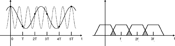
If the base band spectra and the shifted spectra overlap (as a result of the multiplication of the time domain signal with an impulse train), two sine waves with two different frequencies might result in the same sampled signal after the reconstruction.
- Play Quartet
- Original (sampled at 16kHz)
- Play Quartet with aliasing
- Aliased (every second sample removed without filtering)
Before entering the realm of subband coding, the two most important multirate operations are introduced:
Downsampling
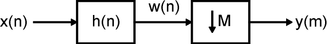
If the sampling rate has to be reduced, care has to be taken that no aliasing will appear at the new, lower sampling frequency. Therefore a digital pre-filter has to be used in order to band limit the input signal to one half of the lower target sampling rate before any samples may be removed in the decimator.
Upsampling
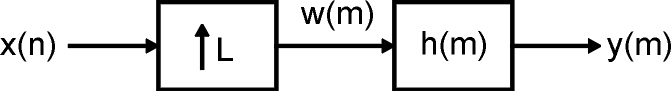
If an increased sampling rate is required, new sample points between existing ones have to be created using interpolation techniques. New zero-valued sampling points are filled in between existing sampling points. Values for these intermediate sampling points are then generated by the digital interpolation filter.
It is important to understand that upsampling followed by downsampling is not necessarily the same as downsampling followed by upsampling, even if the overall ratio of sampling rates may be the same.
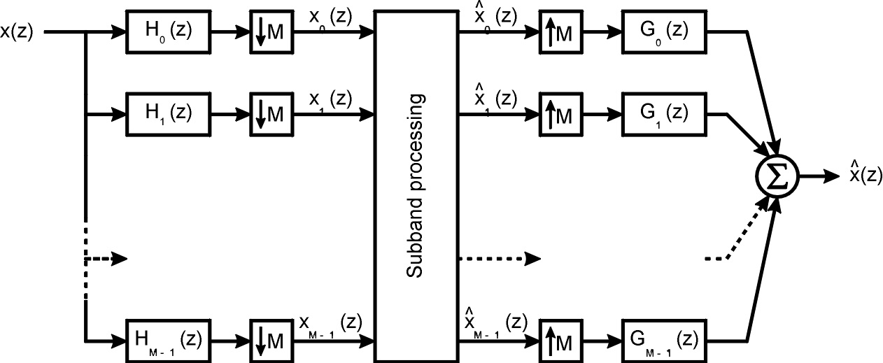
Subband coding
Combining upsampling and downsampling, a subband coding system can be derived, showing an analysis part, splitting the input spectrum into the subbands and the synthesis part which fits together all subbands and generates a broadband signal again.
For the purpose of audio coding, an ideal subband coding system should offer ideal decorrelation of the signals, mimic the critical band behavior of the human auditory system and have no additional overhead. Unfortunately, brickwall bandpass filters in a subband coder can be considered modulated versions [2] of a brickwall prototype lowpass filter and hence are impossible to implement.
Nevertheless, critically sampled system (systems in which each subband is sampled at a sampling frequency equal to twice the subband bandwidth) can be built in which aliasing is completely removed even though the individual subband signals may contain aliasing components. Some of these filters offer perfect reconstruction (PR) [1] and others have a non-flat overall frequency response, i.e. they introduce linear distortions.
Examples are
- QMF (Quadrature Mirror Filters): 2-band, linear-phase, non-PR
- GQMF (Generalized QMF): 2-band, linear-phase, PR, but synthesis filters differ from analysis filters
- CQF (Conjugate Quadrature Filters): 2-band, non-linear-phase, PR, synthesis filters are time-reversed version of analysis filters => they are "orthogonal"
- PQF (Polyphase Qudrature Filters): N-band, modulated, non-PR
- TDAC, MDCT, MLT [6]: N-band, modulated, PR, usually (but not necessarily) orthogonal
In order to provide a sketch of one filterbank, the time domain aliasing cancellation (TDAC) principle is briefly outlined:
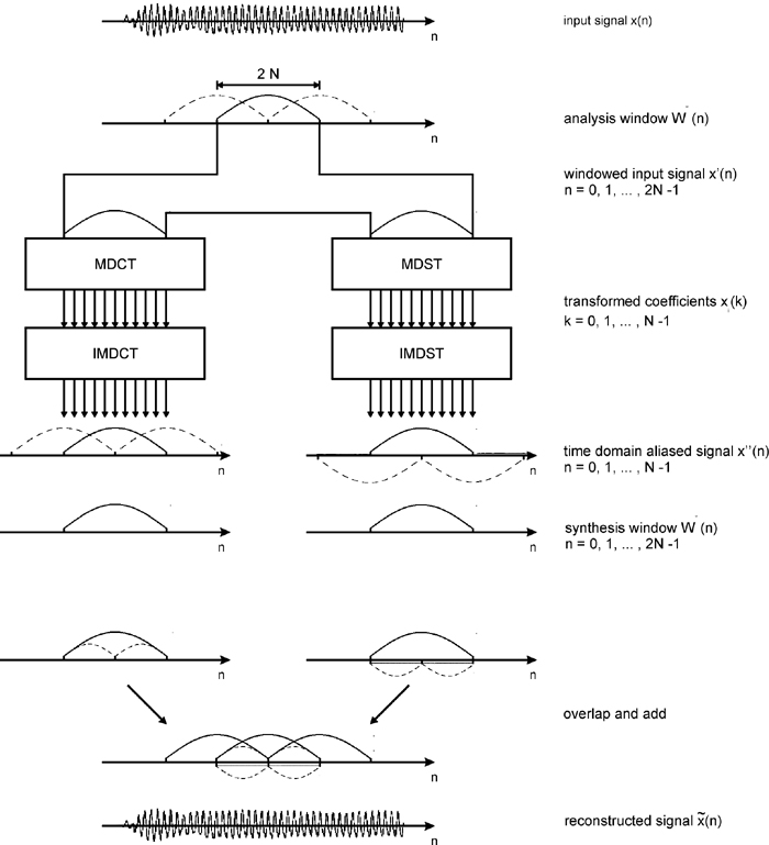
The time domain signal is windowed using a window length of twice the number of subbands, N, and with a 50% overlap between successive blocks. The windowed signal is transformed using a Discrete Sine Transform (DST) and a Discrete Cosine Transform (DCT) where, after the corresponding inverse transforms, the reconstructed time domain signal will contain aliasing distortion. The aliased terms which, for easier explanation, are shown (dashed line) separately from the signal, are time-reversed. Using a synthesis window and an overlap-add approach, these aliased terms will cancel and perfect reconstruction can be achieved.
It should be noted that the TDAC approach illustrated in Figure 5, as originally published in [4], utilizes alternating DCT and DST transforms. More recently, processing with an oddly stacked MDCT transform, as published in [5], has become more popular, requiring only one type of filterbank.
The following subband filter schemes are used in some current audio coding schemes:
- MPEG-1/2 Layers 1 and 2 use 32-band PQF
- MPEG-1/2 Layer 3 uses 32-band PQF followed by 6 or 18 band TDAC in each of the 32 bands
- MPEG-2/4 AAC uses 1024 or 128-band TDAC (refer to the pre-echo section for block size and window switching)
- Dolby AC-3, ATRAC, WMA use MDCT or TDAC-based schemes with different number of bands
Although aliasing is cancelled in the complete analysis-synthesis system, special problems occur in cases where the subbands are further decomposed in a cascaded filterbank. In these cases, aliasing components generated by downsampling are in the "wrong" passband of the following stage and therefore are not attenuated any further.
Examples for subband filter schemes using cascades of filters are:
- discrete wavelet transform [6]
- wavelet-packets
- "hybrid" filterbank of MPEG 1/2 Layer3, which therefore uses an "aliasing reduction" stage
Figure 6 illustrates the structure of an inverse discrete wavelet transform.
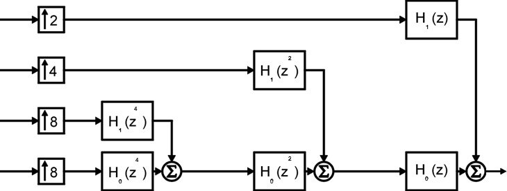
Figure 7 illustrates the problem of aliasing into different bands, as described previously. If we look at the ideal and the real subband filter characteristics, it can be noticed that for the resulting subband filter F, sidelobes will appear. In addition to the ideally desired subband (centered around ~0.22), aliased versions of the signal appear above the desired subband (up to ~0.33) and an additional sidelobe below (around ~0.06).
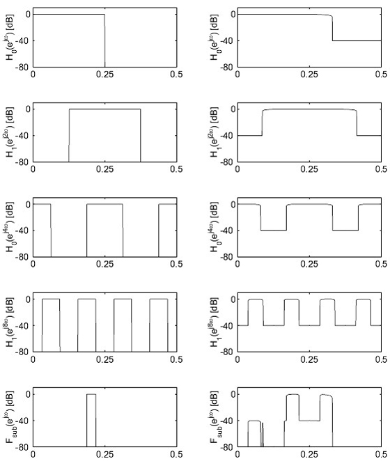
There are two effects of this aliasing:
- there are more spectral components to be coded (e.g. a sine wave produces multiple spectral components) and therefore the coding efficiency decreases
- quantization noise introduced into a specific subband creates noise at different frequency locations.
This is due to the fact that the temporal support of these wavelet coefficients is only of length 10..50 and therefore basis functions of length 50 are used in order to approximate the audio signal. Because FIR filters of length 50 exhibit a limited stopband attenuation, aliasing may appear in the sidelobes of the filter in the stopband regions. These sidelobes may be sufficiently separated from the passband in order to create aliasing in frequency regions with very little signal energy and where the aliasing may not be masked [7].
- Play Flute
- Original
- Play Flute coded
- wavelet filter of length=4, 64 subbands
- Play Flute coded
- wavelet filter of length=40, 64 subbands
Keywords
Aliasing, critically sampled filterbank, Time Domain Aliasing Cancellation, Modulated Lapped Transforms, Wavelets, Downsampling, Upsampling
Further Reading
Filterbanks, Wavelets, Subband modification
References
[1] Vetterli M., “Filter Banks allowing Perfect Reconstruction”, Proc. IEEE SP, Vol. 10, No. 3, April 1996, pp. 219-244
[2] Nussbaumer H., “Pseudo QMF Filterbanks”, IBM Technical Disclosure Bulletin, 24, 19981, pp.3081-3087
[3] Malvar H., “Signal Processing with Lapped Transforms”, Artech House, Norwood, 1992
[4] Princen J. and Bradley A. "Analysis/Synthesis filter bank design based on time domain aliasing cancellation," in IEEE Transactions on Acoustics, Speech, and Signal Processing, vol. 34, no. 5, pp. 1153-1161, October 1986
[5] Princen J.; Johnson A. and Bradley A., "Subband/Transform coding using filter bank designs based on time domain aliasing cancellation," Trans. IEEE ICASSP '87, Dallas, TX, 1987
[6] Blatter C., “Wavelets, eine Einführung”, Vieweg, 1998
[7] Erne M., “Perceptual and Near-Lossless Audio Coding based on Signal-adaptive Wavelet Filterbank”, AES 106-th Convention, Preprint 4934, May 1999
Note: Some of the audio source excerpts have been taken from the SQAM CD [Cat. No. 422204-2] by kind permission of the European Broadcasting Union (EBU)